I also wanted a winder that could run unattended so I could work on other things.

The Motor and Bobbin Mount:
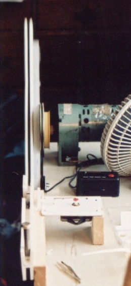
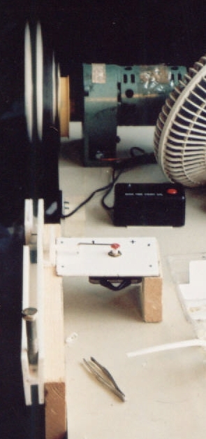
I bought a surplus 120V continuous-duty 100 rpm motor online. I was looking for a fairly low speed motor because I am winding large bobbins, up to 18 inches, so the tip speed gets fast. I wanted to err on the side of control, since the motor can be replaced with one of higher rpm easy enough. I added a simple standard wall switch in a standard rectangular wall box for an on off switch. I set up a small ac fan to blow on the motor to keep it from overheating. I made the bobbin mount by bolting a 18" piece of aluminum square "U" bar to a pulley that matched the shaft of the motor. When I made a bobbin I used the mount as I guide for drilling mounting holes in the bobbin. The pully's shaft set screw allowed me to adjust the finished bobbin assembly in or out on the motor's shaft to align it with the wire guide which, like the motor, was solidly bolted to a countertop/cabinet I bought at a secondhand shop for $5.
note: in the picture you see two pulleys, because I had already mounted the aluminum bar on a pulley for a smaller motor, and rather than go through the trouble of realigning the bar on a new pulley, I just bolted the old pulley to the new pulley.
The Counter:
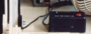 I bought a surplus resetable excercise/jogging counter designed to be strapped to you and count steps, as well as "laps" and elapsed time. The counter also started automatically when triggered and paused automatically if not triggered for a few seconds to save power. The triggering device itself was a mercury tilt switch attached to the circuit board. I clipped this off and replaced it with a surplus magnetic proximity switch, normally used for triggering alarms on windows and doors. I attached a magnet with contact cement near one end of the aluminum bar and used double stick tape to align the switch with it as it passed the table edge during the rotation. This has worked fine, and the automatic start saves having to start it coincidentally with the motor, an extra bonus.
 The Wire Guide:
The wire guide had to not only guide the wire reliably onto the bobbin, but create tension on the wire so that it wound tightly onto the bobbin, and a bit trickier, slowly guide the wire back and forth over the narrow width of the bobbin to get a even buildup across the bobbin instead of the wire building up in one spot. The wire is only the width of a thick hair, so even a bobbin a 1/4 inch wide might be 50 winds across.
I used pieces of the same "I" beam shaped plastic 10' fence panel connectors (lowes/home depot) I used for my bobbins. There were three parts to the guide, which which matched up when fit together to make a continuous guide, since they were all made of the same stuff.
Starting at the end farthest from the motor, I used a piece about 8" long to recieve the wire from the spool, which sat on the floor beneath it. The wire pulls naturally off the top of the spool at it sits there. After it enters the guide, I used a bolt just large enough to screw down into the plastic channel by hand. A small block of plastic that fit into the channel was placed under it. A small piece of stick-backed felt was placed in the bottom of the channel and on the bottom of plastic block. The wire was fed between the bottom of the channel and the bottom of the block, the bolt hand tightened down to squeeze the wire between the layers of felt. The pull of the motor as it wound prvided the tension and I adjusted it to be tight as possible without breaking the wire. The piece had to be 8 inches long to so the tensioner holding the wire in one spot in ther middle of the channel wouldn't create too much resistance for the next stage, which was moving the wire back and forth in the channel.
 The next stage, the "tracking guide", was a nice bit of work. I cut a 3" piece of the plastic and cut a 1/4" hole through slightly above the the bottom of the channel. I used a short scrap of the plastic to make a rod, carving one end to slip easily through the 1/4 hole and span the channel. I used a hot pin to punch a small hole through the rod to guide the wire inside the channel. Now I needed to move rod back and forth in the channel. I used a standard small clock mechanism powered by a "AAA" battery, which I mounted on a small piece of whiteboard, which I mounted on a couple scraps of wood next to the guide, the clock "face" pointing up with the level of the hands about the same as plastic rod. I discarded the minute and hour hands, then I cut the "hand" from the second hand, leaving only the red disk in the center, in which I drilled a few small holes at slightly different distances from the center. Finally, I bent both ends on a piece of brass brazing rod to make a short linkage rod. One end of the rod slips into one of the holes in the clock disk, the other slips into a hole in the end of the plastic rod. I had to bend several linkage rods till I got it to fit just right so that the pinhole at the other end of the rod was lined up in the channel. The clock disk revolves at 1 rpm, which moves the rod back and forth inside the channel, 30 seconds each way, with the moter at 100 rpm, there are 50 turns of wire a pass. Though this wasn't any exact spacing, it was adequate to provide for a even buildup of wire in the bobbin.
The final stage was simply to lead the wire away from the tracking guide while keeping the rising and falling motion of the wire as the bobbin rotated from reaching the rod and possibly widenning the hole in the soft plastic or causing the rod to bind by lifting up on the rod. The clock motor isn't strong and will just slip if there is too much resistance to it's motion, so the rod has to move easily. All I did was drill a small hole to fit a short piece of brazing rod at about the same level as the pinhole in the rod. The piece of brazing rod absorbs the lifting motion of the bobbin and keeps the wire feeding straight out of the pihole in the rod while not redarding its back and forth movement.
The final step was to line up the three pieces and screw them to the side of the table so that the bobbin just cleared the end of the guide nearest it. Since the bobbin was slightly narrower than the original piece I made it from, the piece of sticky felt on one side of the channel is there to narrow the channel slightly.
I have used pieces of a plastic "I" beam used to join sections of plastic fencing, which I found cheap at the local building supply stores. It is easy to work, and if I decided to retain them as part of the final pickup, rather than removing the coil from the bobbin, they would be easy to shape to mount the magnets or whatever. I also wanted to try casting the coils in epoxy just so they would be strong enough for me remove them from the bobbins. The epoxy wouldn't stick to the delron-like plastic material I found. Then I could handle the coils while experimenting with configurations of magnets and cases while I was still experimenting with prototypes. Bobbins could be made out of wood, plastic, or metal, but are usually incorporated into the finished pickup with the coil, which I will do once I know what I want as a finished configuration, though I may still use this plastic, or plastic, as again, easier to work with than metal.
Practically, I simply took the "I" beam and sliced off one side of it with a handsaw, then bolted it back together as I bolted it to the aluminum bar. This way I could take it apart afterwards. It also allowed me to adjust the height of the coil as well by further trimming down the center seperator before bolting the two halves back together. I may try to use some sort of thinner sheet plastic and some sort of plastic bar and bolt together a bobbin where I have even more control of the height of the coil. Or I could shape the plastic "I" beam to it's final configuration before I wind it. Experimentation will see whether it is easier to modify the present material or easier to build out of seperate pieces, whether it is easier to remove the coils from reusable bobbins and mount them into a pickup or wind them on a permanent bobbin that is incorporated into the finished pickup.
The plastic bobbins worked to make free-standing coils I could use for multiple configurations, but after that, I moved to permanent bobbins that provided more strength and stiffness in the fnished pickup and less chance of damaging the coil in the building process.
My first permanent bobbins are made from aluminum channel bar like I used for the mounting bar, but a smaller size. I might have tried using steel but I couldn't find anything light enough readily available at the local big-chain hardware stores, while aluminum bar was. I cut the entire bar lengthwise to closely match the finished coil, and then cut a notch in both ends to hold the wire. I was able to wind the first bobbin just like that, but the wire is still quite loose on the bobbin (I may be able to fix that eventually) and doesn't stay lined up over such a long length. So I added sides to the aluminum bobbin with poster paper braced with construction board to hold the wire in place till I could pot the coils, in wax this time. I layered in a sheet of aluminum foil with the poster paper to use as shielding on the finished coil. I used a piece of solid aluminum sheet instead of poster paper, which I could form a complete case for the coil by beding the sides down after I potted the coil.
As for the future, the aluminum worked well enough to use as a standard, but I can still try steel, which will effect the magnetic field. I can also try tapping holes in the aluminum bar corresponding to the strings and scew in steel pole pieces that I can adjust in height like an electric guitar.
Materials and Costs
main motor : $30.00 (C&H Sales)
clock motor : $ 5.50 (All Electronics)
excercise counter: $ 2.65 (All Electronics)
large pulley : $ 3.75 (All Electronics)
magnetic switch : $ 3.00 (All Electronics)
fence panel joiners : $ 6.97 (local retail building supply)
aluminum bar, brazing rod : unrecorded, minimal cost (local retail building supply)
TOTAL: under $50.00
Suppliers
C and H Sales - surplus electronics and machinery
All Electronics - a great source of discount surplus electronics parts, switches, magnets, jacks, plugs, motors, piezo elements, cables and wire among other things.
MWS Wire - #42 plain enamel covered wire for handwinding pickups
The Magnet Source - all types of magnets
other handwinder sites:
http://designed2wind.alphalink.com.au/ - DIY high quality winding machines
http://www.cinternet.net/~rewinder/
http://www.harpamps.com/micKdiy/DIY-Coil-Winder.html
Pickup sites:
http://mywebpages.comcast.net/skgs/sk/Index.htm
http://tomacorp.com/pickups.html
http://users.chariot.net.au/~gmarts/index.html - good general site
http://www.guitarnuts.com/index.php
http://europa.spaceports.com/~fishbake/fpickup/pickup.htm
http://www.harmony-central.com/Guitar/electric-construction.txt
http://www.harmony-central.com/Guitar/other.html#gui
http://www.penmachine.com/musicpages/guitartone.html
http://www.skguitar.com
http://www.ampge.com